Wear protection deep inside the bore.
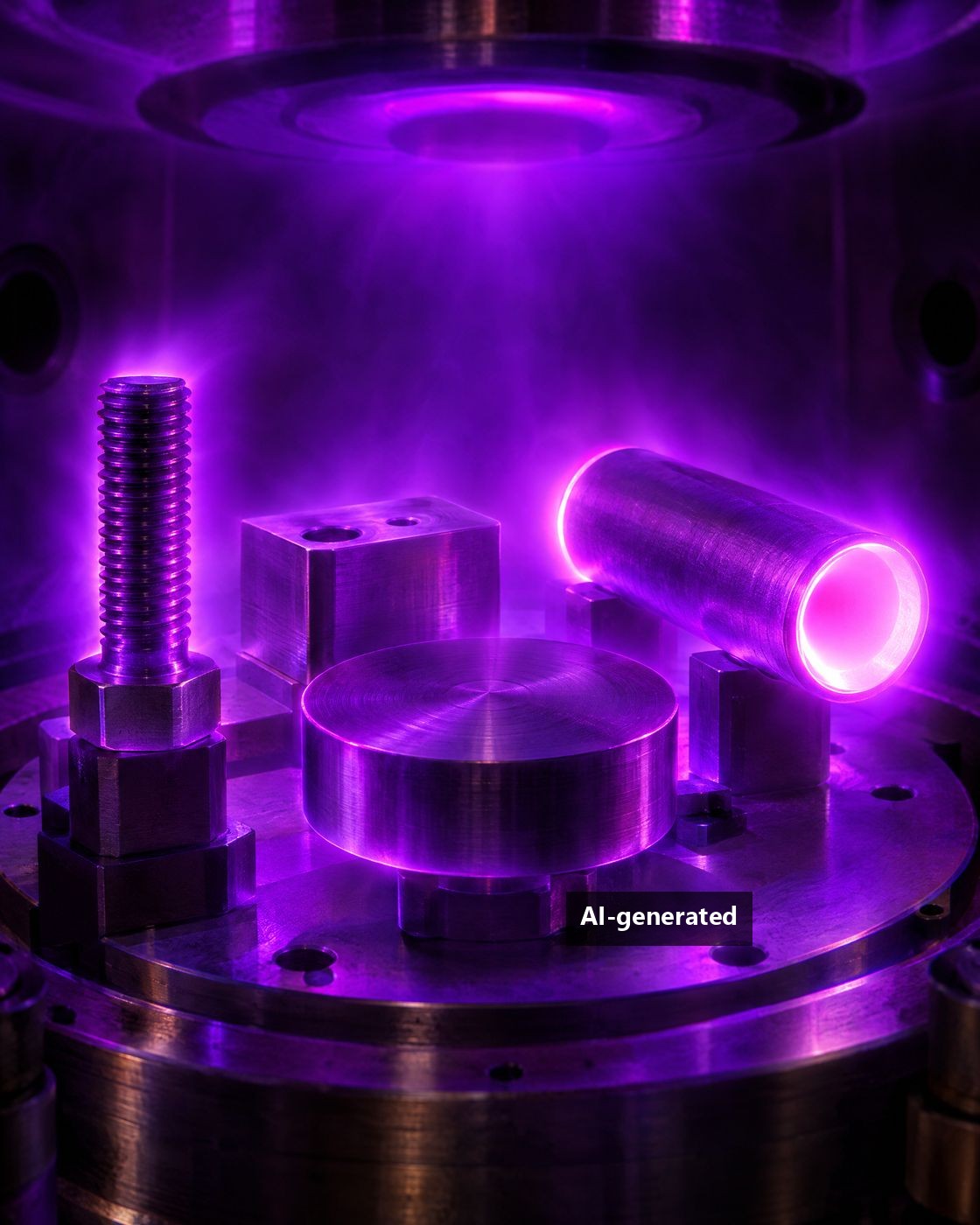
With DLC XTENDED® we coat the inner surfaces of bores, nozzles and pipes – from 3 mm inner diameter, at inner diameter to length ratios of up to 1:40 and component lengths of more than one metre.
- from 3 mmInner diameter
- up to 1:40Inner diameter to length
- >1,000 mmComponent length
- up to 10 µm/hDeposition rate on the inner diameter
- ~1,100 HVCoating hardness DLC XTENDED®
Where components wear from the inside.
Friction, abrasion and build-up often attack functional surfaces exactly where conventional coating processes cannot reach: inside bores, nozzles and pipes. PVD processes work in line of sight – with narrow, long internal geometries the inner surface remains largely uncoated. With PACVD we bring the plasma directly into the bore.
Less wear
The hard, amorphous carbon coating protects highly stressed inner surfaces against abrasion and adhesive wear – for longer service life.
Less friction
A low coefficient of friction and low tendency to build-up ensure consistent sliding and flow behaviour – even with insufficient lubrication.
Higher load capacity with DUPLEX
Combined with PLASNIT® plasma nitriding, a diffusion zone supports the hard coating – for high contact pressures and impact loads.
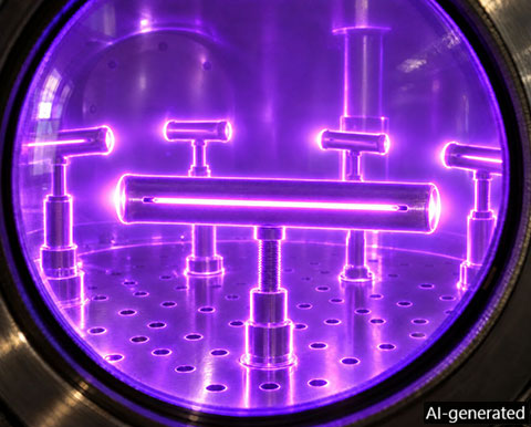
Symbolic image – this is how we analyse the process: a slot in the test tube makes it visible through the sight glass how the plasma burns in the inner diameter.
Plasma that reaches deep inside.
Plasma inside the component
The component is connected as the cathode in a vacuum. With a suitably selected process pressure, the glow discharge burns not only on the outside but also in the inner diameter. There we achieve deposition rates of up to 10 µm/h – many times that of the outer surface.
DUPLEX: nitriding and coating
On request, we first create a diffusion zone of 0.1–0.2 mm with PLASNIT®. The DLC XTENDED® coating grows on top of it – the hardened surface zone prevents the hard coating from collapsing under load.
Process tailored to your geometry
How uniform the coating is along the length depends on the inner diameter and the component length. We tailor the process parameters to your component:
Process pressureGas mixturePulse frequencyLoadingAuxiliary anode
Does your component fit?
Enter the inner diameter and length of the bore to be coated. We classify your geometry against the results of our previous projects and trials.
Guide value based on previous projects and trials. No commitment – the binding assessment is made after a sample coating.
The right coating for your inner surface.
DLC XTENDED®
Our proven amorphous carbon coating – the standard for internal coating.
- Hardness
- ~1,100 HV
- Coating thickness ID
- 4–16 µm
- ID
- from 3 mm
DUPLEX PLASNIT® + DLC XTENDED®
Plasma nitriding and coating combined: the diffusion zone supports the coating.
- Diffusion zone
- 0.1–0.2 mm
- Compound layer
- 3–4 µm
TiN
Titanium nitride for internal geometries – first aerospace components successfully coated.
- Coating thickness ID
- 13–18 µm
- ID
- from approx. 8 mm
TiBN / TiCN
Titanium boron nitride and titanium carbonitride: we are currently refining the deposition parameters for internal geometries.
- Status
- R&D
From the fine nozzle to the metre-long pipe.
A selection of components we have already coated internally – with typical geometries.
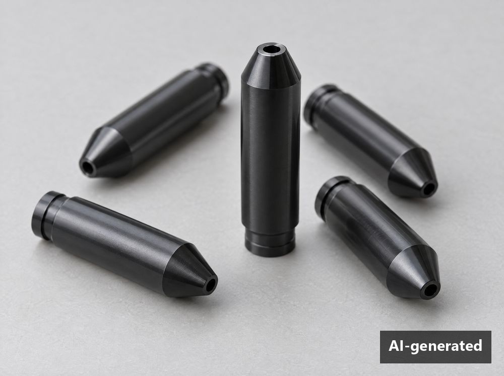
Nozzles
Fine nozzle bores against abrasive wear; cold spray nozzles with L/ID 1:50 in preparation.
Ø from 3 mm · L/ID up to 1:40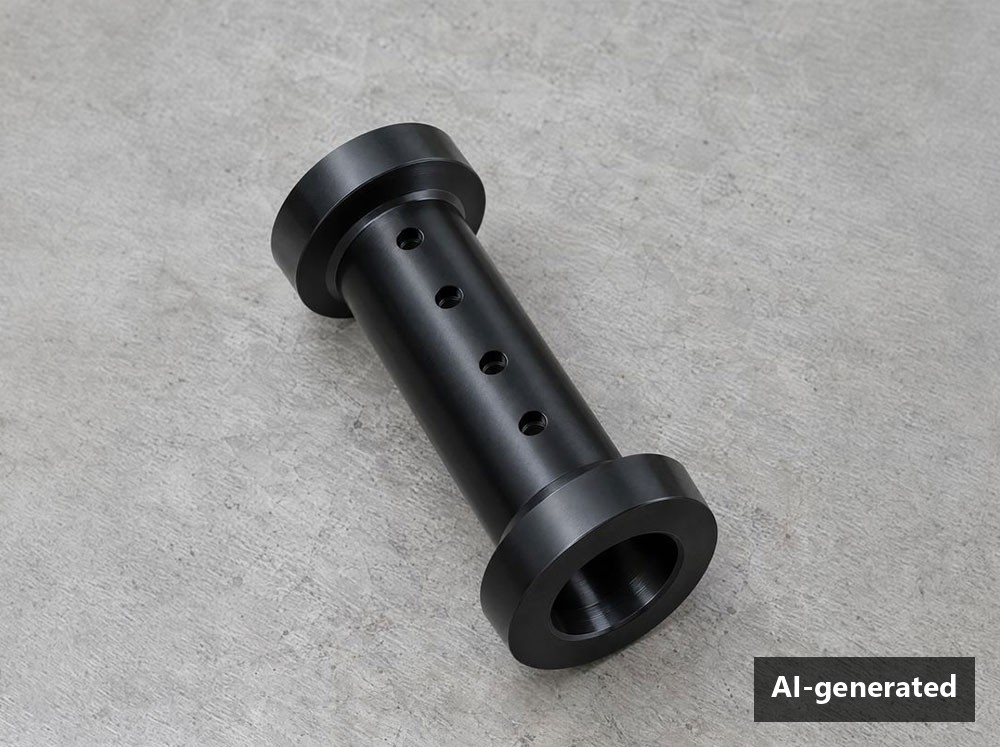
Bushings & guides
Sliding and guide surfaces with a uniform coating inside.
Ø 6–13 mm · L 80 mm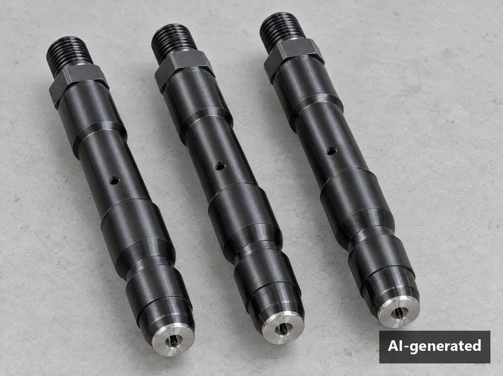
Injector & valve bodies
High-pressure bores in injection and fluid power technology.
Ø 11 mm · L 120 mm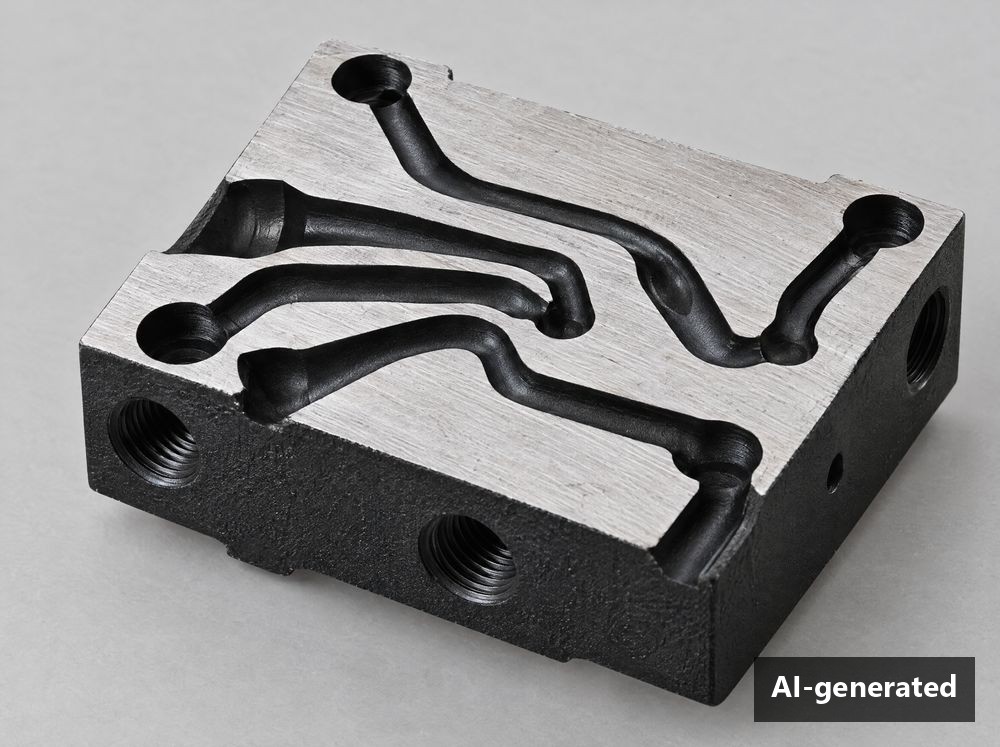
Additively manufactured components
Complex 3D-printed internal channels, down to the finest cross-sections.
Ø from 3 mm · L 130 mm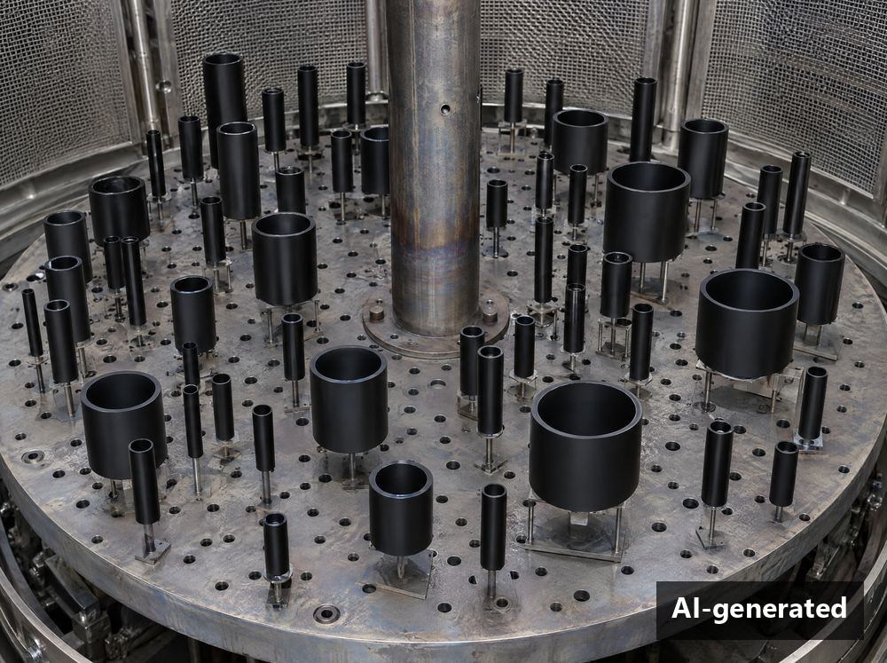
Precision tubes with high L/D
Long tubes with a narrow inner diameter – with special loading and auxiliary anode.
Ø 17–22 mm · L 700 mm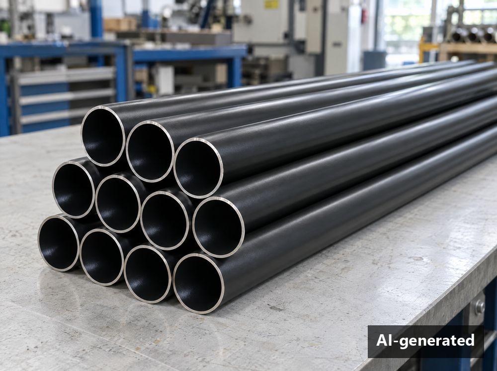
Heat exchanger tubes
Protection against deposits and wear in the media flow.
Ø 25 mm · L 400 mm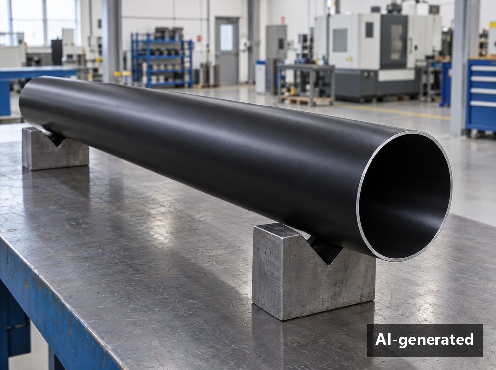
Large stainless steel pipes
Long pipes with a large inner diameter – with auxiliary anode in the ID.
Ø 100 mm · L 1,110 mm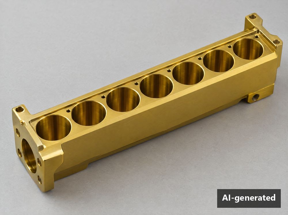
Housing bores
Bores in structural components, e.g. from aerospace – with TiN.
Ø 8 mm · L 58 mm“Confidentiality is our top priority. As many customers come from security-critical industries such as aerospace, we show only AI-generated symbolic images here. The geometry data comes from real projects.”
- Aerospace
- Hydraulics & fluid power
- Injection technology
- Energy technology
- Mechanical engineering
- Security & defense technology
- Hunting & sports
700 mm tube. Measured, not estimated.
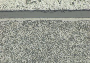
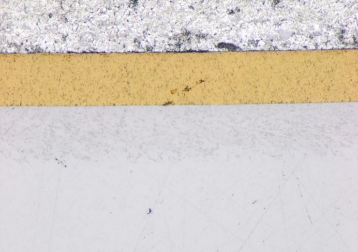
A precision tube around 700 mm long shows how much the right loading makes a difference: with our special loading, the coating thickness in the middle of the tube triples.
Precision tube, DUPLEX-treated
Mean values from 10 measuring points each, DLC coating thickness on the inner diameter, microscopic according to EN ISO 1463.
- Diffusion zone
- 0.1–0.2 mm
- Compound layer inside
- 3–4 µm
- DLC coating inside
- 6–11 µm
- Coating hardness
- ~1,100 HV
Four steps to series production.
Enquiry
You send us the drawing, material and requirements for the inner surface.
Sample coating
We define the loading and the process and coat sample parts.
Laboratory testing
Cross-section, coating thickness along the length and hardness profile – at the RUBIG Competence Center.
Series production
With the approved process, we coat your components reproducibly in series.
Your component wears from the inside? Let’s talk about it.
Our coating team checks your geometry and proposes the right coating system – confidentially and without obligation.
